Designing Winterbloom's Castor & Pollux
Back in July of 2020 I began working on Castor & Pollux, a Roland Juno-inspired oscillator. Since opening pre-orders in October it's become an incredible success for Winterbloom. This post will focus on the hardware design of Castor & Pollux- including the schematics, layout, and component selection. My hope is that this will be relatively accessible to anyone with a little bit of electronics knowledge, but, if you find something confusing or unclear please feel free to reach out.
Before jumping in, I wanted to make sure that you know that Castor & Pollux's hardware design and firmware are completely open source. You can find the source files on GitHub.
Eurorack?
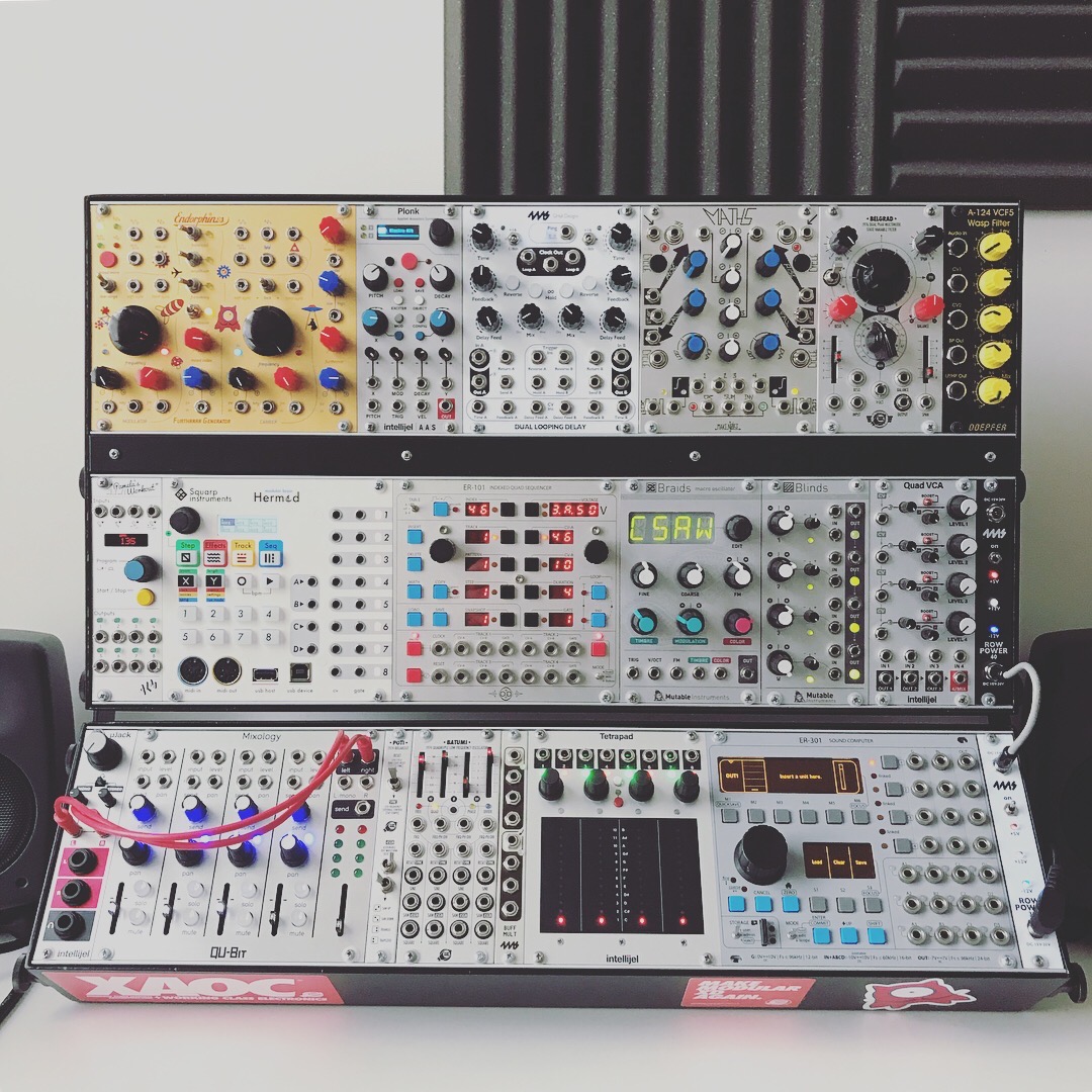
Castor & Pollux is a Eurorack module. If you aren't familiar with Eurorack, no worries! Eurorack is a modular synthesizer format- basically, instead of having one big synthesizer you have a bunch of smaller modules and you route signals between them to control how the synthesizer works, and therefore how the synthesizer sounds. Castor & Pollux is an oscillator, a sound source that can be controlled by other modules.
A quick overview of the module
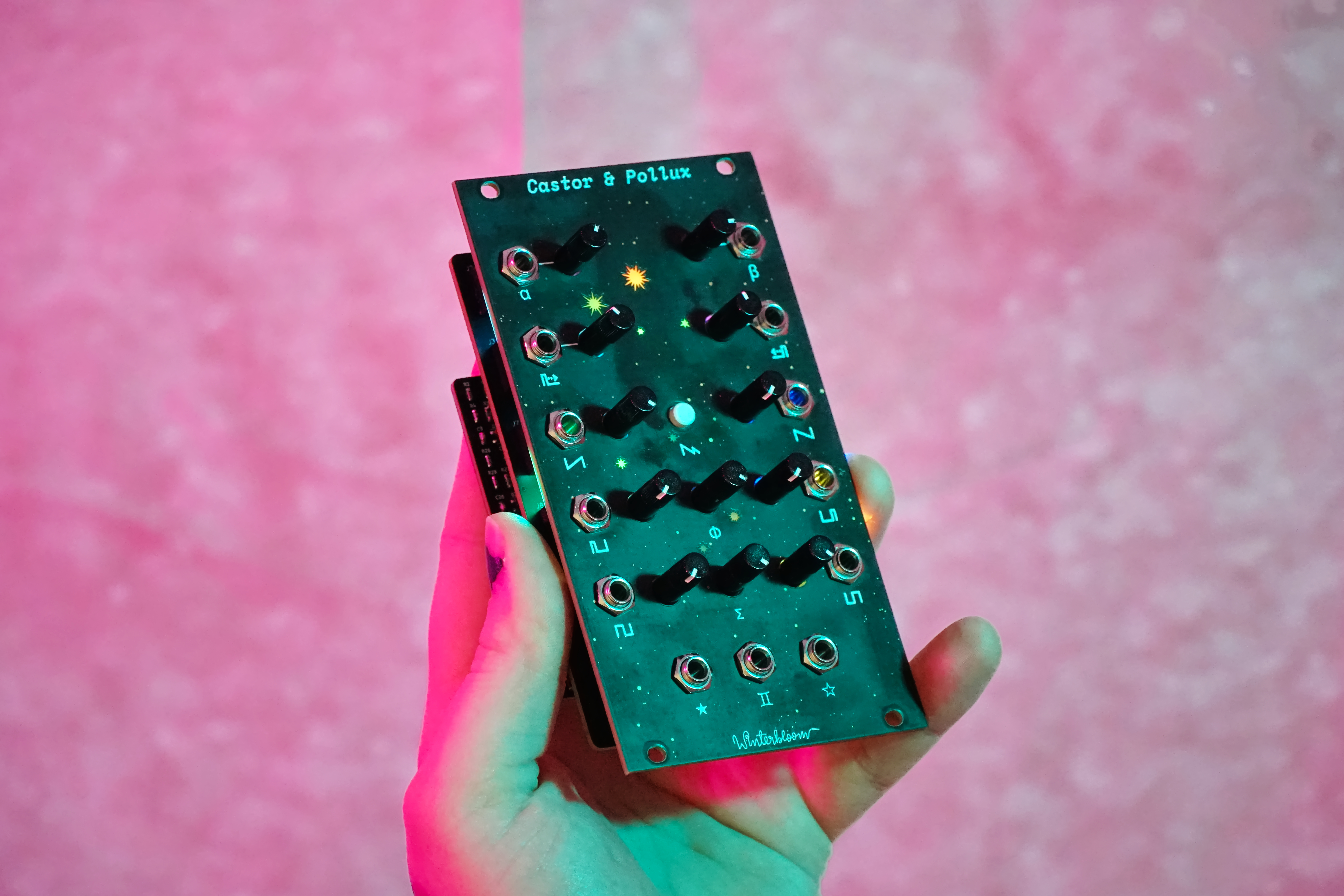
Before diving into the hardware design it's useful to have a basic understanding of what the module does. The final design of Castor & Pollux looks like this:
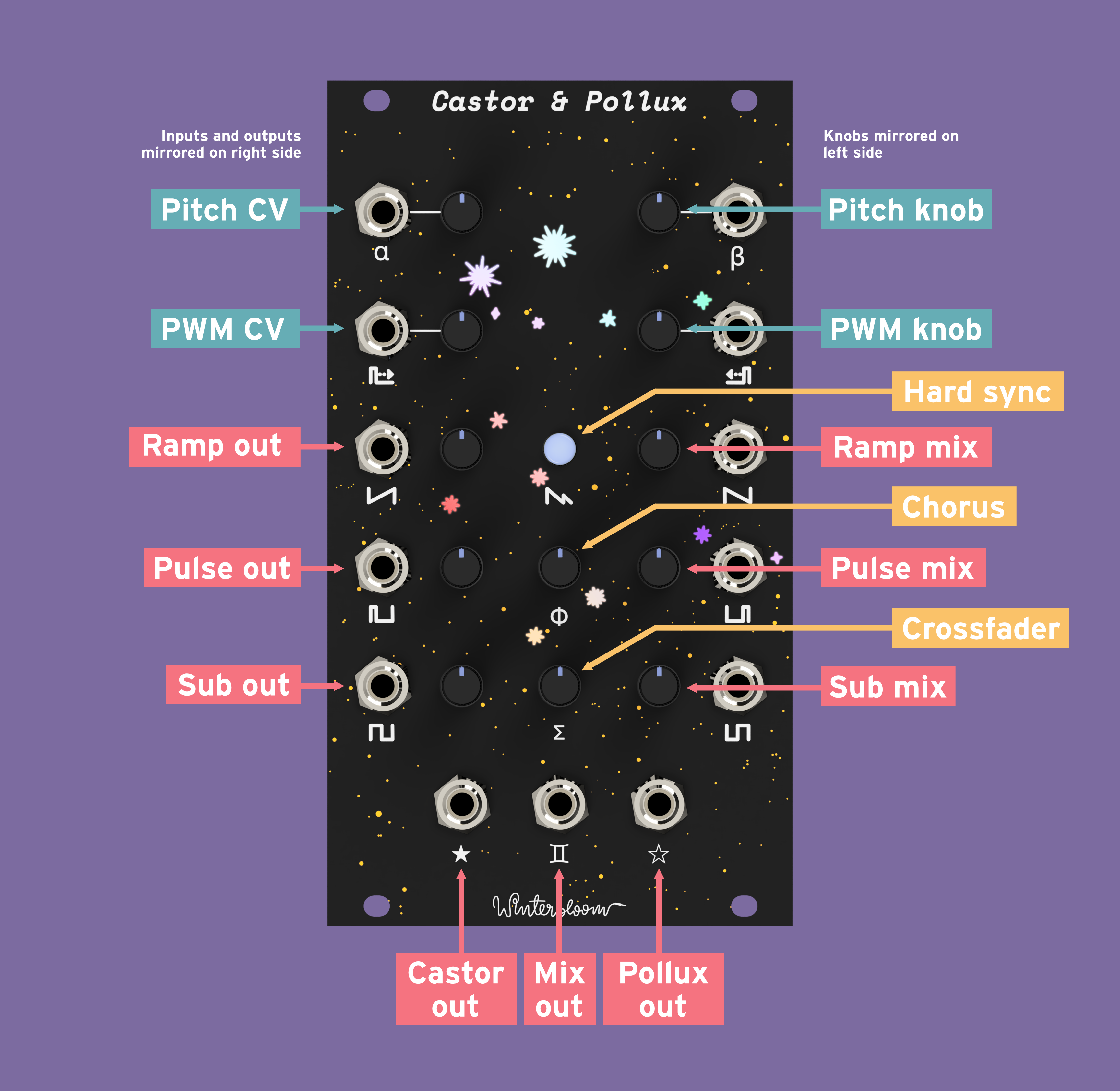
A stand-out feature is that it has two separate oscillators. That means that many parts of the user interface and the circuit are doubled.
Each oscillator has two inputs: one to control the pitch and another to control the pulse width (or duty cycle) of the pulse waveform. There are also complementary knobs to control those parameters.
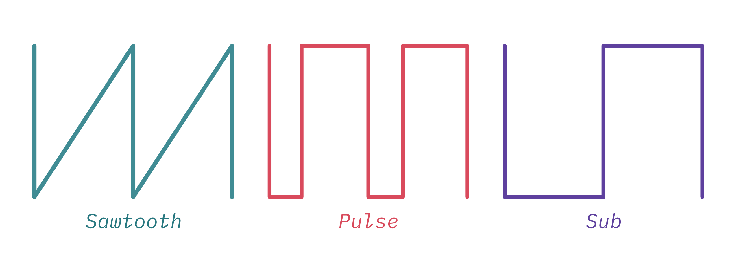
Each oscillator has 4 outputs. Each of the three waveforms (sawtooth, pulse, and sub) have a dedicated output. The fourth output is a mix of the three waveforms. The volume of each waveform can be set using a knob for each.
In between the two oscillators there's an output that combines the mix from both oscillators. This output can be blended from one oscillator to the other using a knob as a crossfader.
Finally, there's a knob for controlling the internal low-frequency oscillator (LFO) and a button to enable hard sync.
If you want to get a really in-depth guide on Castor & Pollux and all of its features you should check out the user guide.
Getting started
I often get a lot of questions like "How do you start a project like this?". For Castor & Pollux, I started with inspiration - the Roland Juno - and went from there. I generally like to write down a vision for each project, and my vision for Castor & Pollux was:
Create a spiritual successor to the Roland Juno's voice for Eurorack
From there I started thinking of how to realize that vision. If I wanted to isolate a single piece of the Juno that defines its voice to bring to Eurorack, I'd have to pick the sound source, the oscillator. The filter and chorus circuits play a huge role in the Juno's sound as well but I felt those were outside the scope of a single-purpose module.
From this point I started working on a block diagram of the key, high-level pieces that go into the module. I started pretty abstract- something like this:

And then I spent quite some time research and experimentation to further develop and break down the design into concrete bits.
Research, experimentation, & iteration
In order to bring my idea to life, I initially did a lot of research and experimentation around the Roland Juno's oscillator. I basically went through and learned everything I needed to know to understand how the oscillator worked, its limitations, and how I could put a little of my own magic into it.
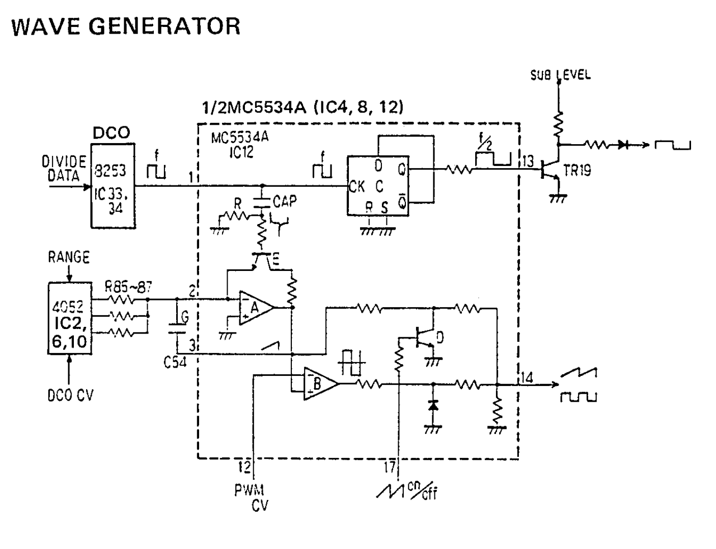
This starts with the schematics from the Juno and goes all the way to building out the oscillator on a breadboard and onwards to designing a printed circuit board for it. During that time I did a lot of just learning - I learned a lot about op amp integrators & comparators, flip-flops, and more. This knowledge culminated with a deep understanding the Juno's oscillator- enough to write an in-depth analysis of it and begin designing my own. I very much recommend reading through the analysis - it provides some really great insight into how all of these components fit together.
At the end of all this I'd taken that high-level block diagram and broken it down into a more concrete system outline:

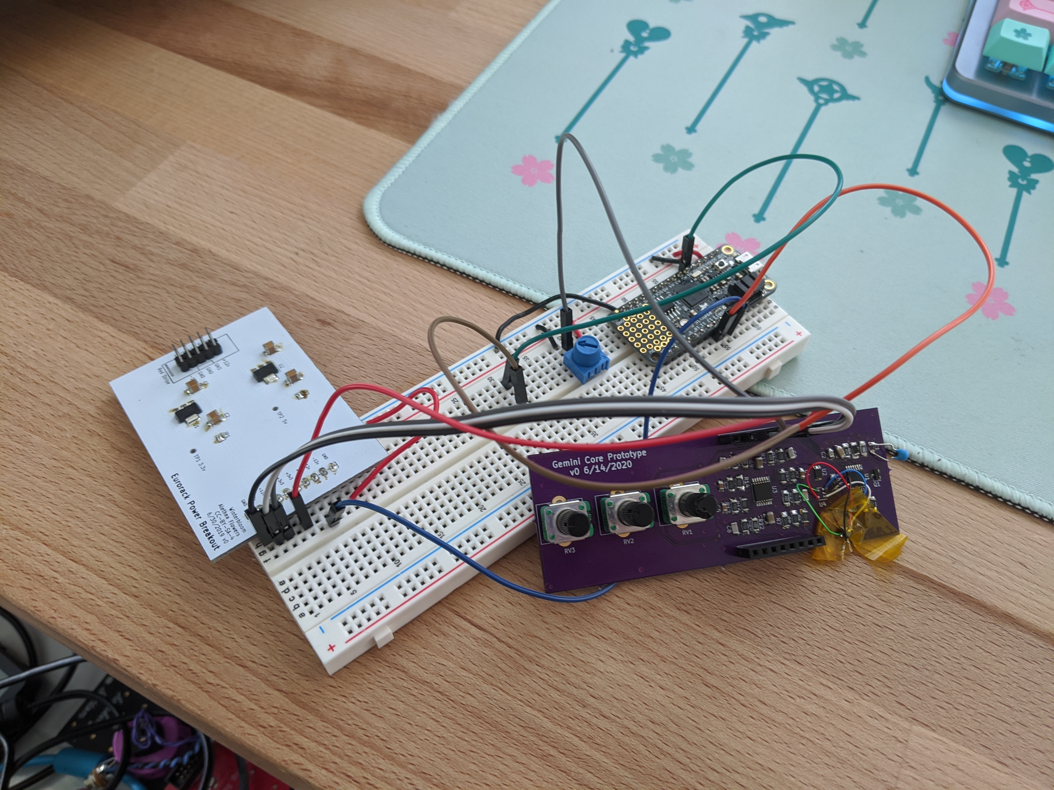
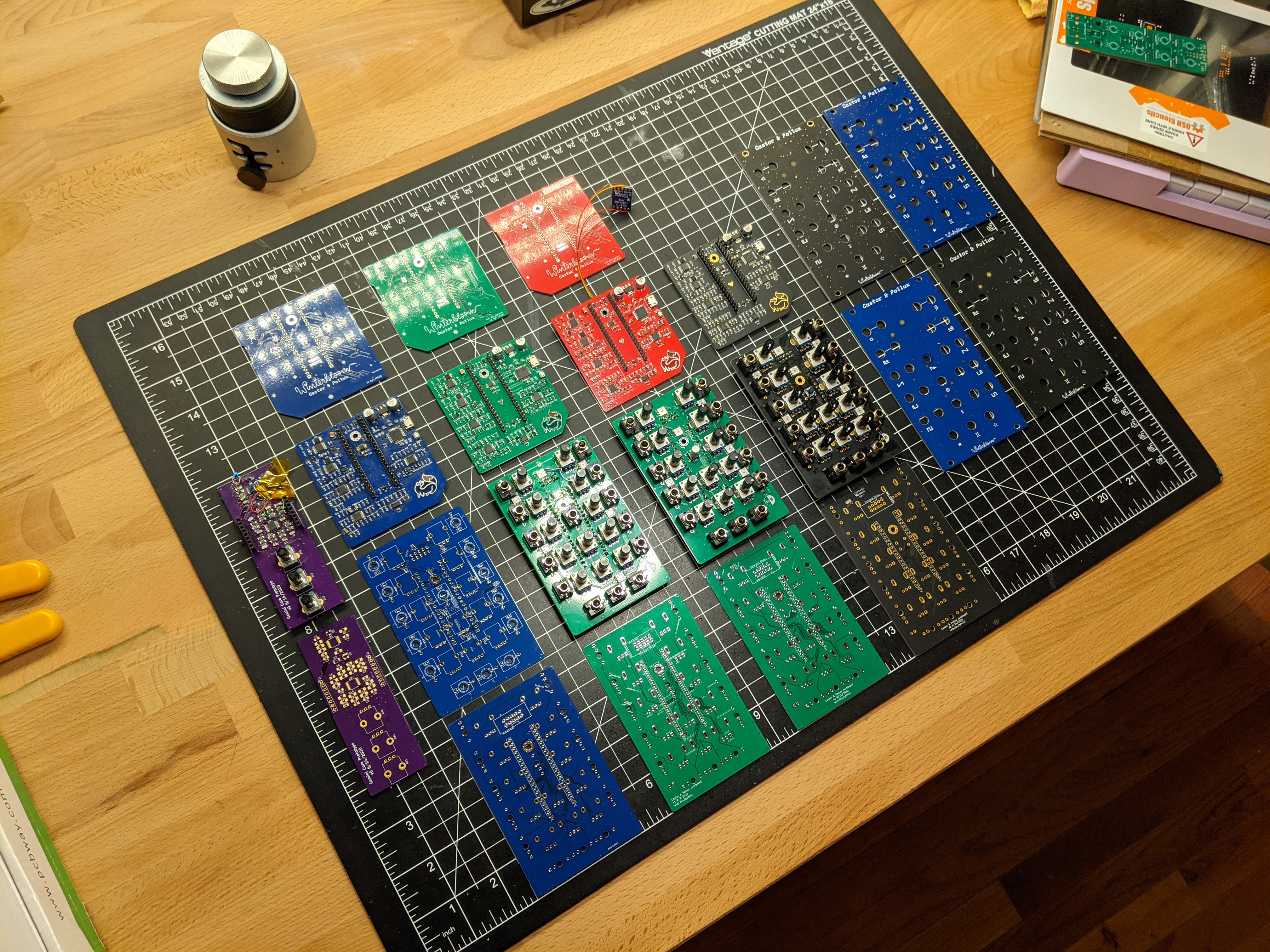
And I'd also created some prototype circuits and boards:
At this point I felt confident enough to start developing the full project. Now that I had a general idea of the major parts of the system and the circuits involved I started researching components. I researched voltage regulators, op amps, DACs, microcontrollers, and interface components such as potentiometers and pushbuttons. I generally track all of this research in Notion- I gathered datasheets, made notes, laid out specifications, created comparison tables, etc. I also printed out datasheets and highlighted and annotated specific spots that are relevant.
This is also when I started making some concrete decisions about the design, specifically around the inputs and outputs and how I wanted people to be able to interact with it. I established some key properties:
- Two oscillators over the Juno's one. I didn't just want to replicate the Juno, I wanted to give it something unique.
- Independent outputs for each oscillator's sawtooth, pulse, and sub waveforms.
- A built-in mixer to allow combining the waveform shapes without needing another module.
- A crossfader to combine the two oscillators.
With all of that groundwork done I started iterating on the hardware. This can be quite a test of patience as making changes often involves waiting a week or so for new boards to be manufactured and delivered. To help with that, my approach is to try to do as much as I can with the board I have before ordering a new revision. This often leads to "bodges" where I've changed components, connections, fixed errors, etc. Once I feel confident in the changes I'll order a new revision and continue iterating.
All-in-all Castor & Pollux took five total revisions to get to the point where it was "production ready". While I won't go into detail on how I changed things between interations, the following sections will give you insight into the final design.
Power
Power is a good place to start with any design. The Eurorack "standard" provides a power cable with +12v, GND, and -12v. While analog circuitry is happy to work with the 12 volt supplies, Castor & Pollux also contains a microcontroller and it needs a much lower 3.3v. In many other situations this is where I'd typically reach for a switching DC-DC converter, however, since the module consumes very little overall current and because I wanted to avoid noisy switching converters I opted for a linear regulator. I went with the venerable LM1117- it's an excellent low-noise regulator. The key parameters here are:
- A high power supply rejection ratio (PSRR) of
75dB. To grossly simplify, this is how much upstream voltage noise the regulator can block from the downstream components. This is important because Eurorack power supplies tend to be switching regulators and the power rails are shared with other modules so they are generally pretty noisy. - A fairly accurate and stable
1%voltage output over its temperature range -3.235v-3.333v. This is useful since Castor & Pollux needs to accurately read voltages using an analog-to-digital converter and a stable input voltage goes a long way to improving accuracy.
The biggest drawback to using this is that there is a bit of wasted heat to get rid of and the regulator requires relatively high-value capacitors on its output to ensure stability. For the wasted heat, I was careful to ensure that the overall current draw wouldn't cause the regulator to go into thermal overload. I also added a significant copper area to the board to allow the regulator to dissipate heat more effectively.
For the output capacitance, the datasheet calls for a 10uF tantalum capacitor but I don't generally like to use tantalum capacitors in my designs. Therefore, I went with low equivalent series resistance (ESR) aluminum electrolytic capactors. These take up a bit of space but they're worth it for the additional stability.
To finish it all off there are reverse-polarity protection diodes and some ferrite beads to help filter out any high-frequency noise from upstream.

The brains
Unlike a lot of other oscillators that are purely analog or purely digital, Castor & Pollux is a hybrid. It needs a relatively simple microcontroller to handle controlling the analog oscillators. Since I already had a good deal of experience with Microchip's SAM D series, I decided to use the SAM D21 as the brains for Castor & Pollux.
I love the SAM D21. It's such a wonderful little processor. It can run at up to 48 MHz and can have up to 256 kB of flash and 32 kB of SRAM. That's more than enough speed and room for Castor & Pollux's needs. It also has some nice features like a built-in multichannel analog-to-digital converter (ADC), 24-bit timers that can output PWM signals, flexible serial interfaces, and USB.
Overall, the microcontroller needs to:
- Read the interface inputs such as the pitch input jacks and knobs.
- Generate the initial square wave for each oscillator at the proper note frequency.
- Generate two control voltages for each oscillator: one to charge the oscillator's integrator and another to control the oscillator's pulse width (I'll cover both of these a bit more in a later section).
Castor & Pollux's schematic is about as bare-bones as it gets for the SAM D21- it's largely just the chip itself and some bypass capacitors. To help with programming, testing, configuration, and firmware updates, I also added a USB port. This is all largely covered in the datasheet's Schematic Checklist (section 44):

To generate the four control voltages (two for each oscillator) I added an external MCP4728 four channel, 12-bit digital-to-analog converter (DAC). The reason for using an external DAC is that the SAM D21 only has a single built-in DAC. I picked the MCP4728 because it's a widely available, inexpensive, and broadly used part and there wasn't any reason to use anything fancier. The MCP4728 talks i2c and it's connected to one of the SAM D21's SERCOMs:

The front panel has some RGB LEDs (dotstars) and inputs from the jacks and potentiometers. The LEDs are connected to one of the SERCOMs and the inputs are routed to different channels for the SAM D21's built-in ADC:

Finally, two of the SAM D21's timers (TCCs) are used to create a square wave signal that's used by the oscillators:

One thing I did consider was including a crystal oscillator to give the SAM D21 more accurate clocks and timing. It turns out that for audio-frequency stuff that really isn't all the necessary and the built-in oscillators on the SAM D21 are more than accurate enough. So that saves some space and cost.
The heart
If the microcontroller is the brains, the oscillators are the heart. Castor & Pollux has two oscillators based on the Juno design. There's a lot of research and thought that went into this part of the project and I once again recommend reading my Juno DCO analysis if you want the full picture of how all of this works.

The central piece of the oscillator is the ramp core. It turns the square wave from the microcontroller into a sawtooth waveform. This design is realized using the tried and true TL074 op amp configured as an integrator:

Notice that this requires two signals from the microcontroller - a square wave with the frequency of the intended note (generated by one of the SAM D21's timers) and a control voltage to control the rate of charge for the integrator's capacitor (generated using the MCP4728).
The oscillator also generates a sub waveform - a square wave at half the frequency of the note - by dividing the input square wave by two. Dividing a square wave "clock" signal like this is relatively easy using a D-type flip flop. It's kinda funny to use a digital logic IC for creating an analog waveform, but it's a very clean and simple implementation:

The specific part used here is the 74LVC2G74. If you aren't familiar, this part is a member of the ubiquitous 7400 series logic chips. The LVC designates the subfamily - in this case it means the chip can run on 1.65v - 3.3v and has 5v tolerant inputs. The 2G74 designates the specific logic chip - in this case it's a single D-type flip flop.
Finally, the oscillator generates a pulse waveform with a variable pulse width. It does this by using a comparator along with a control voltage from the microcontroller (generated by the MCP4728):

There's a nice deep explanation of how this works here, but to put it visually:
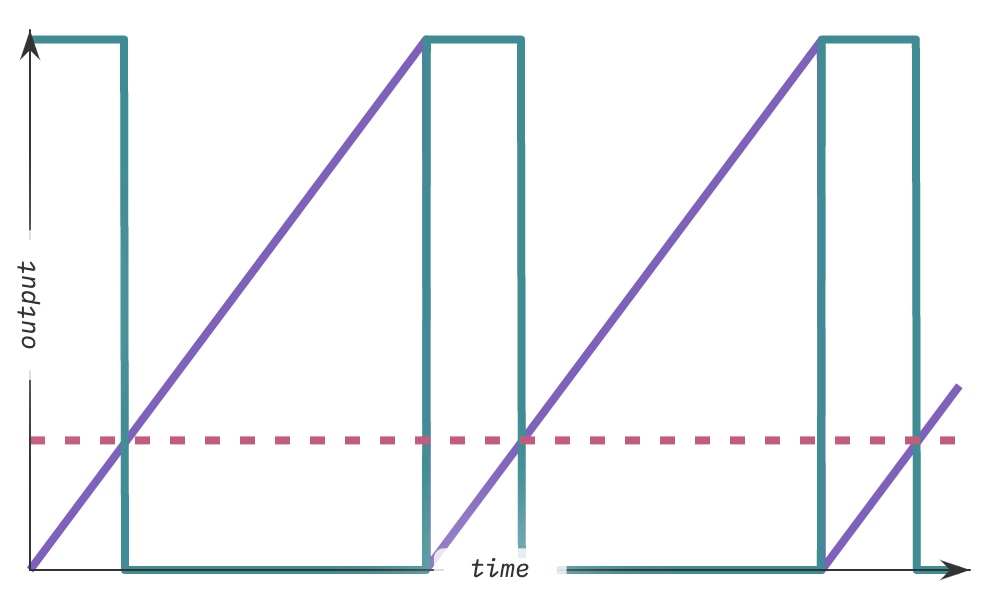
The red dotted line is the control voltage, the saw waveform is in purple, and the resulting pulse waveform is in teal. Whenever the saw waveform's level is below the control voltage the output is high, and conversely, whenever its above the control voltage the output goes low. The higher the control voltage, the longer it the output stays high, therefore increasing the pulse width.
Outputs
With all of the waveforms generated the signal now flows to a series of output amplifiers. These handle removing the DC offset from the waveforms and amplifying them to 6v peak-to-peak as expected by other Eurorack modules. Here's the schematic:

Each amplifier is identical. The raw waveform signal enters on the left, passes through a high-pass filter to remove the DC offset, and then gets amplified using a straightforward inverting amplifier configuration. Finally, there's a current-limiting 1kΩ resistor between the amplifier output and the jack so that temporary shorts when connecting and disconnecting patch cables don't cause any trouble.
Note that once again I'm using the tried and true TL074. While there are certainly "better" op amps available, the TL074 is ubiquitous, low cost, and well understood. I just like it. :)
Each oscillator also has a mixer that lets you mix the three waveforms together into a single output. Each waveform has a potentiometer to control its volume in the mix. The mix is routed to its own output jack on the front panel- once again, through a 1kΩ current-limiting resistor:

The mixer is a implemented using a summing inverting amplifier, also known as an "active mixer" or "virtual earth mixer". It's a very common circuit to see in audio applications.
Finally, Castor & Pollux has a crossfader that allows blending the output from the two oscillator's mixers together. This is implemented using a clever little circuit that allows blending between two inputs with a single potentiometer:

An explanation on how this works is a little outside of the scope of this article, so I recommend reading through this article if you're super curious.
Control voltage inputs
Castor & Pollux has a pitch CV input and a pulse-width CV input for each oscillator. The pitch CV is 1v per octave and can be between 0v (indicating the lowest note) and 6v (indicating the highest note). The pulse-width CV has a range of 0v (indicating 0% pulse width) to 5v (indicating 100% pulse width). These are measured using the microcontroller's built-in analog-to-digital Converter (ADC). However, the ADC can only handle voltages between 0v and 3.3v. Therefore these inputs have to be scaled down to the ADC's range.
Since the scaling required here is relatively simple, you might think to use something straightforward like a voltage divider. While that might be perfect in some situations, it's not ideal here because signals in Eurorack can be anywhere between -12v and +12v. If you were to feed voltages outside of the nominal 0v-6v (or 0v-5v) range through the voltage divider the ADC would be subjected to overvoltage and most likely damaged.
So for Castor & Pollux I used a slightly more complex approach - one that I also used on Big Honking Button. It involves uses an op amp in a the familiar summing inverting amplifier configuration to scale the input voltage, invert it, and offset it:

The basic idea is that this configuration inverts the input, then scales it based on the gain from the input and feedback resistors (56kΩ / 100kΩ = 0.56), and then offsets it based off a -10v reference scaled by its input resistor and the feedback resistor (56Ω / 169kΩ = 0.33). If you step through the output voltage formula -(Vin * 0.56 + -10v * 0.33) = Vout with the intended minimum and maximum voltages (0v and 6v, respectively) you'll see that it accomplishes the goal of fitting the input range into 0v-3.3v:
- Minimum
Vin:-(0v * 0.56 + -10v * 0.33) ≈ 3.3v - Maximum
Vin:-(6v * 0.56 + -10v * 0.33) ≈ 0v
Notice that the range gets inverted, but that's a simple task for the microcontroller to deal with. For example, when using a 12-bit ADC the microcontroller can figure out the input voltage using the formula Vin = (1.0 - (ADCin / (2^12 - 1)) * 6.0.
The last trick is that the op amp used here, the MCP6004, is a rail-to-rail op amp that's powered from 0v and 3.3v. Since it can't output a voltage beyond its power rails it effectively limits the voltage the microcontroller sees.
User interface
Castor & Pollux has twelve potentiometers and a push button to allow the user to set various parameters. Most of the potentiometers are used control the output circuitry - the mixers and the crossfader. However, five of them are used to set parameters in the microcontroller.
Reading these potentiometers is significantly easier than dealing with control voltage. The potentiometer is connected so that fully counter-clockwise is 0v and fully clockwise is 3.3v and the output of the potentiometer is just sent straight to the microcontroller:

Castor & Pollux also has a push button that can be used to enable hard sync and to access the "tweak" interface. It's also pretty straightforward - it shorts the microcontroller's pin to ground when pressed. When not pressed, an internal pull-up resistor in the microcontroller handles pulling it up to 3.3v:

Wrapping up
So that's most of the important bits of Castor & Pollux's hardware design. I hope that this has been helpful for you. You can find the full schematics here:
Here's some more resources that might be interesting to you:
- The Design of the Roland Juno oscillators - an in-depth analysis of the Juno's digitally-controlled oscillators.
- Designing Winterbloom's Big Honking Button - a similar article about Big Honking Button.
Once again, if you read this and wanted to know more about something or felt something was unclear, please reach out!